MR8 Equipment Reference
This page provides a reference guide to the equipment available in the MR8 suite. For the step-by-step scanning procedure, see the Practical scanning protocol.
Overview and diagram
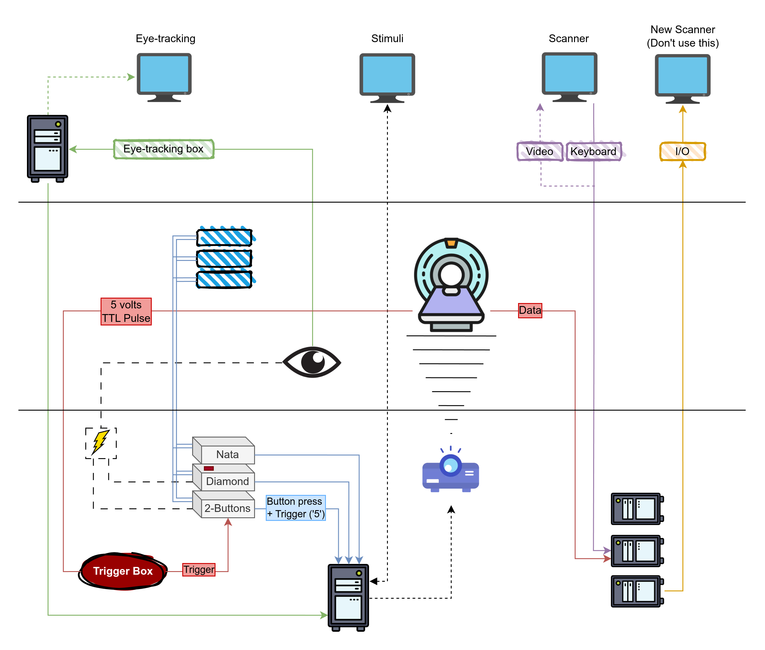
The diagram above provides a (non-exhaustive) overview of the MR8 suite's equipment and how instruments are connected. A more thorough description of the equipment is available in the manual.
Systems are color-coded, and can be read as follows:
- Red lines and boxes indicate connections from the scanner:
- TTL Pulse a.k.a. the "trigger", which is used among other things to synchronize the fMRI task with the scan.
- Data connections from the scanner to the PC.
- Blue lines and boxes indicate button boxes, and double lines represent optical fiber connections. Specifically:
- Nata box, 5 buttons. Important: if you use this box, make sure your code can differentiate between the
5button code and the5trigger code. This can be done programmatically, and it is addressed in recent versions of our scripts. An alternative workaround would be to relay the trigger through the diamond box, which sends theTtrigger code instead of the usual5. If you need to do this, make sure you switch back to the original set-up at the end of your scanning session. - Diamond box, 4 buttons. This box is marked with a red tape. When the trigger box is connected to this box (which should not be the case), this box relays the trigger
Tto the stim PC. - 2-buttons box. When the trigger box is connected to this box (which is the expected and usual set-up), this box relays the trigger
5from the scanner to the Stim PC.
- Nata box, 5 buttons. Important: if you use this box, make sure your code can differentiate between the
- Green lines and boxes indicate Eye-tracking instruments and connections
- Eyelink 1000 long range system, including the camera and infrared light source
- ET box to convert analog input from the EL-1000 to digital.
- ET PC to run the Eyelink software and control recordings and settings.
- Power for the ET system is located in the back room.
- Purple lines and boxes connect the MRI control PC (old system, which we use)
- Gold lines and boxes connect the MRI control PC (new system, which we DO NOT use)
- Dotted lines mostly relay audio/video
- Dashed lines are power lines.
Stimulus PC
The stimulus computer's desktop is located in the control room. It is the second-last computer from the right, between the eye-tracking computer (last) and MRI control computer.
-
Login: Use the provided username and password. Login details can be found here.
Password Not Accepted?
If the password is not accepted, check for a qwerty-azerty keyboard mismatch. Press
alt+shiftand ensure EN is selected on the login screen. -
Experiment files: Store your experiment folders under
C:\Research\Psychology\(create your own folder within this directory). -
Installed software: Matlab 2011b, 2015a, and Psychtoolbox 3.0.123 are installed.
Tip
If Matlab freezes or shows a JAVA error, restarting Matlab should fix the issue.
-
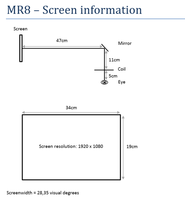
Screen information: To flip the screen, adjust the projector settings, not the computer.
Trigger and button boxes
The scanner sends a trigger "5" to the stimulus computer. Different setups are used for static and dynamic stimuli:
A single wire connects two button boxes, each with 2 buttons:
- Box 1:
- Blue button = Trigger 1
- Yellow button = Trigger 2
- Box 2:
- Green button = Trigger 3
- Red button = Trigger 4
A response box with 4 buttons:
- Blue button = Trigger "b"
- Yellow button = Trigger "y"
- Green button = Trigger "g"
- Red button = Trigger "r"
Check Trigger Outputs
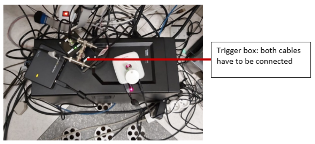
Before starting the experiment, verify that the buttons provide the expected outputs on the stimulus PC screen. If no triggers are working:
- Restart Matlab and/or the stimulus computer.
- Check if any cables have been left disconnected. The response box is on top of the stimulus desktop PC in the control room. Ensure both cables are properly connected.
Button Box Not Responding
- Restart Matlab.
- Reset the button boxes in the technical room by unplugging and reconnecting the power cables.
- If the problem persists, restart the stimulus computer.
Trigger Not Working
- Restart Matlab and check for responses from the button box.
- Ensure the trigger passes through the static stimuli box (check if the boxes are responsive).
- Verify that all cables are connected properly. The response box is on the table next to the desktop PC in the technical room.
Restarting the Scanner
Do not do this without the approval of Ron or Stefan. If the trigger still doesn't work, you may need to restart the scanner:
- Ensure the volunteer is out of the scanner first.
- Go to the technical room and locate the box with the red stop and green start buttons.
- Press the red button to stop the scanner. Wait 10 seconds, then press the green button to restart it.
- Log back into the scanner computer using MRService credentials.
- Wait until all components are ready and restart the software. Confirm any errors, such as helium pressure alerts, by pressing OK.
Scanner table and coils
-
Cover Cushions: Always cover the cushions with paper towels before use.
-
Keep Equipment Off the Floor: Do not place cushions or equipment on the floor. If any are found on the floor, place them on the shelves.
-
Patient Table Setup:
- The 32-channel coil should be placed ~10 cm from the edge of the table.
- Coil connections:
- Left lower plug and right upper plug.
- Headphones: Plug into the upper left connector at the top of the table.
- Panic Button: Plug into the lower left connector at the bottom of the table.
Running Low on Supplies?
If you run out of supplies (e.g., paper towels), you can find new ones in the closet right in front of you when entering MR suite E408. Paper rolls are stored on top.
Projection system
Screen
-
Correct Position: Ensure the back of the screen is aligned with the black marks on the scanner table.
-
Handling: Never touch the projection side of the screen. Use the plastic stand at the bottom if you need to move it.
Projector filter
Ensure that filter 3NB (1.34% light transmission) is placed in front of the projector tunnel for consistency across scan sessions.
MR8 offers four filter options, each with different light transmission levels:
| Filter | Light Transmission |
|---|---|
| 3NB | 1.34% |
| A+B | 4.27% |
| A+C | 4.86% |
| Unnamed (grey tape) | 69.3% |
You can combine filters to adjust the luminance.
Handle Filters with Care
Filters are fragile. Always hold them by the frame to avoid damage. Filters are stored in the top left drawer of the cabinet in the scanner room.
Projector usage
-
Powering On: The projector brand is NEC. Use the remote (button on the top right) to turn it on.
-
Adjusting the Lens: If the lens is out of position, use the buttons next to the lens on the projector to adjust — do not touch the lens directly.
Projector showing blue window or incorrect display
- Check that the projector cable is properly connected to the stimulus computer.
- Ensure the source is set to DisplayPort. Press the DisplayPort button on the remote to reset the projector to standard settings.
Viewing Projector Menu
To view the projector menu, you'll need to be inside the scanner room with the remote. Remove the filter, then use the remote inside the scanner to see the menu options on the projection screen.
Audio system
Yellow headphones
- The yellow headphones are stored on the left side of the storage space (against the wall).
- The headphones will present sound at full level only when placed inside the scanner bore.
- To use them, disconnect the white headphones from the head coil and replace them with the yellow headphones.
Control room microphone
The microphone is always on, but goes into standby mode after a few seconds.
| Button | Function |
|---|---|
| + / - Buttons | Increase/decrease the volume. |
| Menu Button | Access various options. Hold it and press the + button to navigate the menu. |
| Grey Button | Speak to the participant. |
Activate the fMRI settings by holding the Menu button and pressing + to navigate to the fMRI option.
Amplifier and converter
- Check that the red and white plugs (audio cables to the headphones) are connected to the converter.
- Ensure the power cable is plugged in next to the red and white plugs.
Participant Can't Hear You
- Reboot the amplifier by unplugging the power cable underneath the desk.
- Reboot the converter by unplugging its power cable.
Volume Imbalance (left/right)
- Adjust the balance via the Menu button. Hold it and use ± to adjust levels separately.
Eyetracker hardware
The MR8 suite includes an Eyelink 1000 long range eye-tracking system. For the procedural steps on setting up eye-tracking during a scan, see the Eyetracker setup section of the scanning protocol.
- Power: Connect the eyetracker plug to the power supply (marked with a white tag: "eyetracking"). Power is located in the back room.
- Screen alignment: Ensure the screen is aligned with the EYE line.
- Floor marks: Check if the eyetracker setup is aligned with the floor marks.
- Eyelink software: Boot the Eyelink software on the Eyetracker PC (default option in the Windows Boot Manager). If Eyelink doesn't start, press
tfollowed by Enter to launch it manually.